Installing Hebel in apartments
Installing Hebel internal wall systems
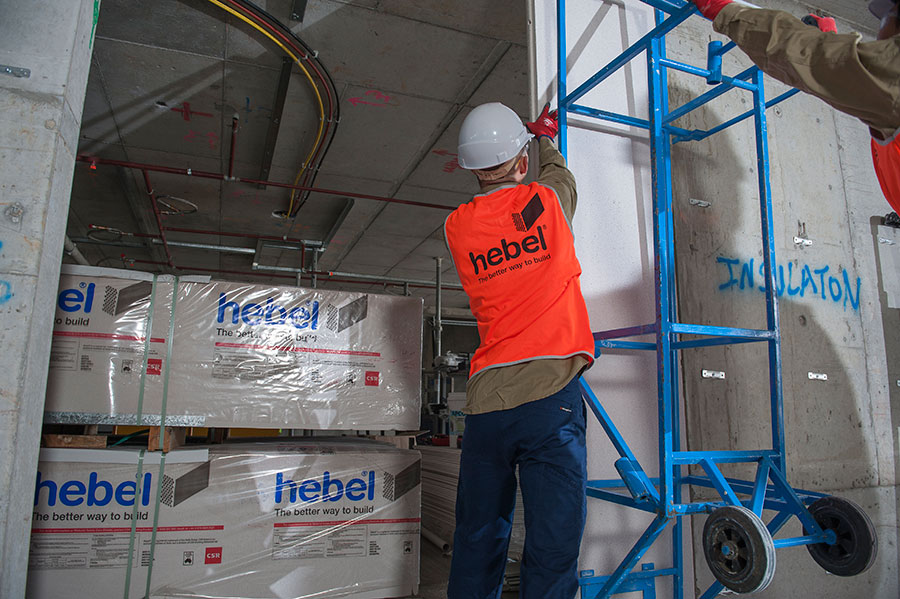
Hebel internal wall systems are fast to install and make fire and acoustic compliance easy. Here we take you through the basic steps in installing a Hebel intertenancy or party wall system. These basic steps also apply to vertical installation of Hebel corridor wall systems and shaft systems with linings for high rise apartments, student accommodation, hotels and commercial projects.
Please refer to the Hebel Design & Installation Guide HELIT117 for further information associated with the installation process including delivery and storage, panel handling, system components and construction details.
PREPARE THE WALL AREA
Before you begin the installation make sure the wall area is clean and clear and the wall positions are set out. This includes marking up the steel stud wall frame position. If there are doors, set out the nib locations now.
HEBEL POWERPANEL WALL LEAF
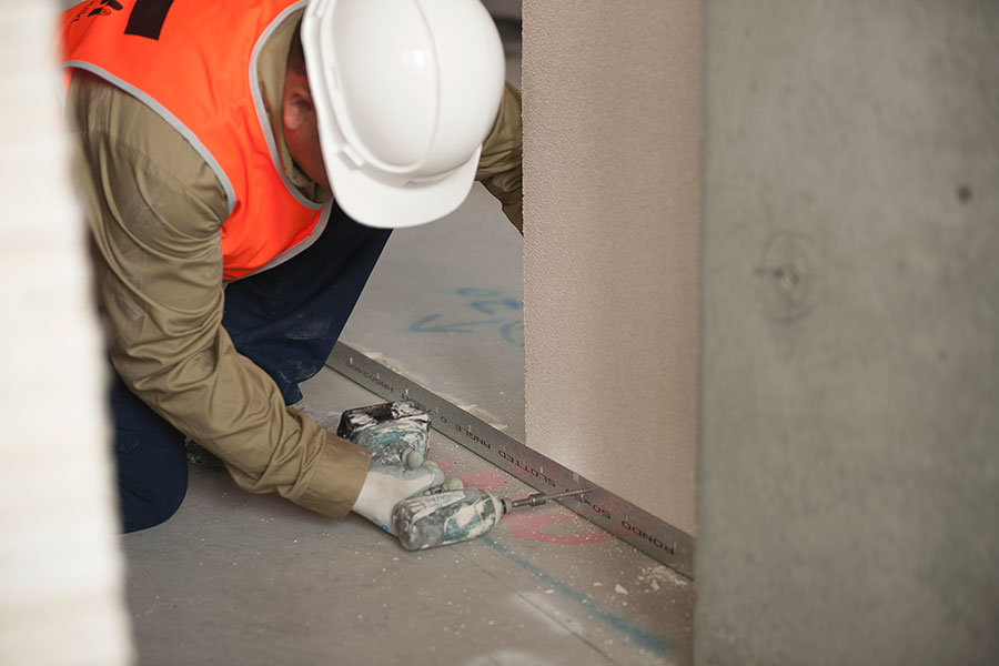
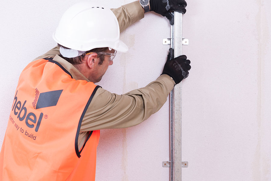
STEP 1 Install head and base angles
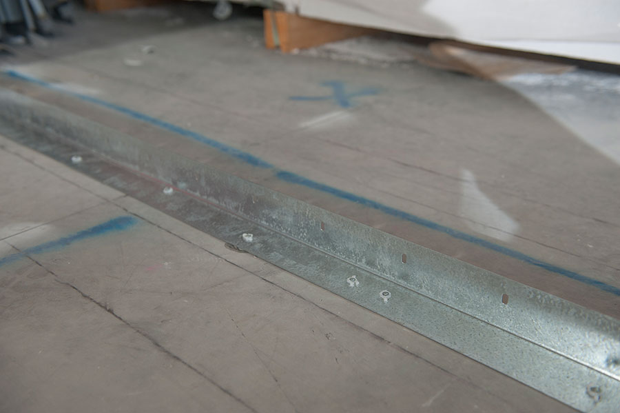
The first elements of the wall system to be installed are the head and base angles which are fixed to the concrete support structures. The purpose of these angles is to position and restrain the top and bottom of the panels with the aid of screw fixings. The angles are slotted to allow the slab to deflect without damaging the wall panels.
- With the correct angles ready (see below or Design and Installation Guide for correct angles) and the wall location set out, cut the slotted steel base and head angles to the required size – using the full length of the angle
- Fix angles to the concrete slab and soffit using appropriate fixings* – don’t over tighten screws
- Butt each angle section together, closing any gaps
- Seal all butt joints in the head angle with CSR FireSealTM
- Make sure the fixings are no more than 600mm apart and no more than 100mm from the end of each angle section.
* Note: The fixings need to be capable of withstanding a shear load of 0.75kN per metre (for wall heights up to 3.0 metres). For high wind pressures the designer should determine if mechanical fasteners are required.
For the head angle (and vertical connections) use a slotted steel angle measuring 75 x 50mm x 1.2mm BMT. This angle is also used for vertical connections as well as base connections when the wall height is greater than 3.3 metres and / or for 2-hour fire-rated systems.
For the base angle there are two types to consider:
- If the wall height is 3.3 metres or under – use a slotted steel angle 50 x 50mm x 0.8mm BMT
- If the wall height is over 3.3 metres and / or a 2 hour fire-rated system is required, use the 75 x 50mm x 1.2mm BMT slotted steel angle at the base.
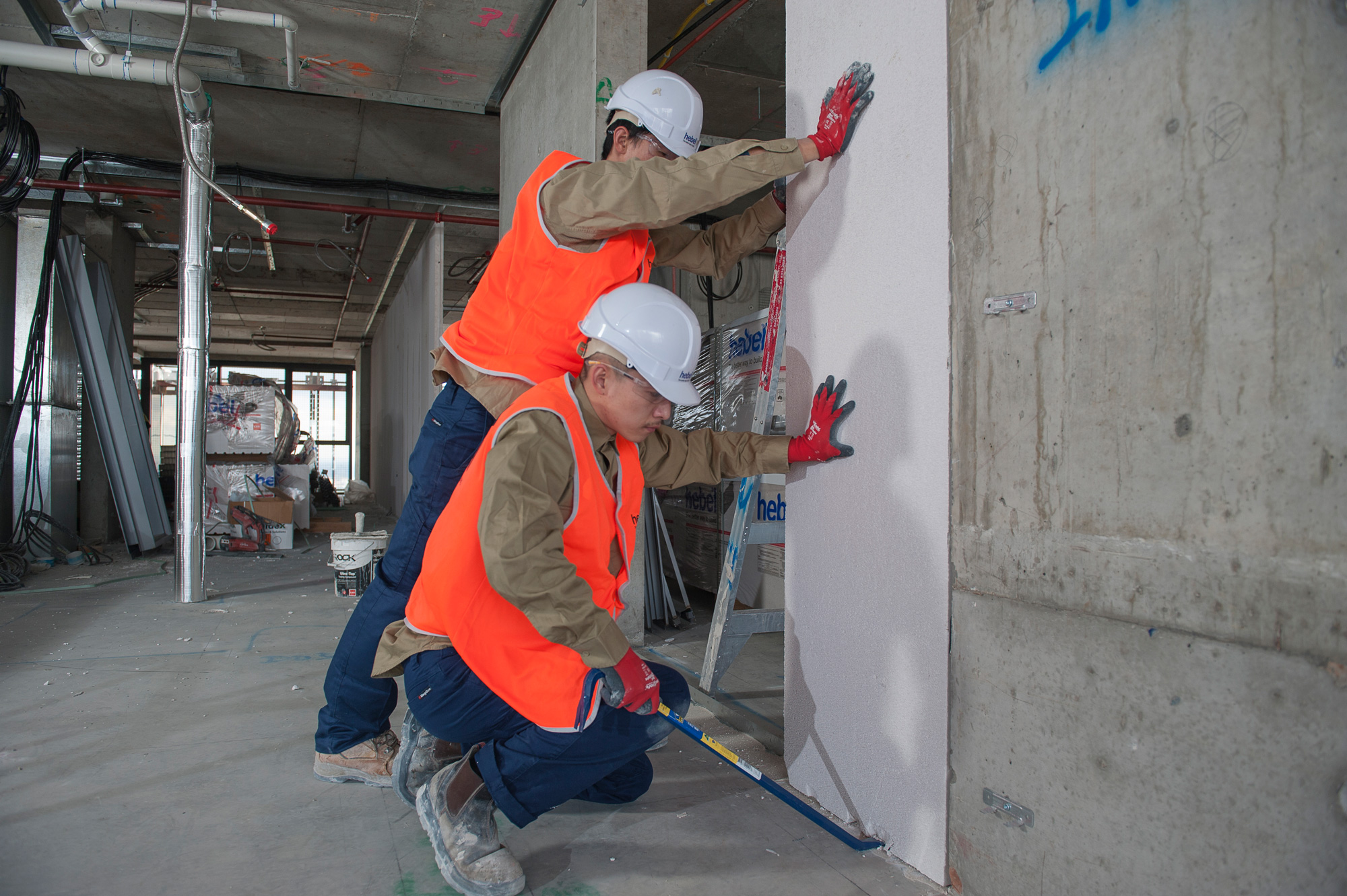
STEP 2 Measure from slab to soffit, cut panels if required
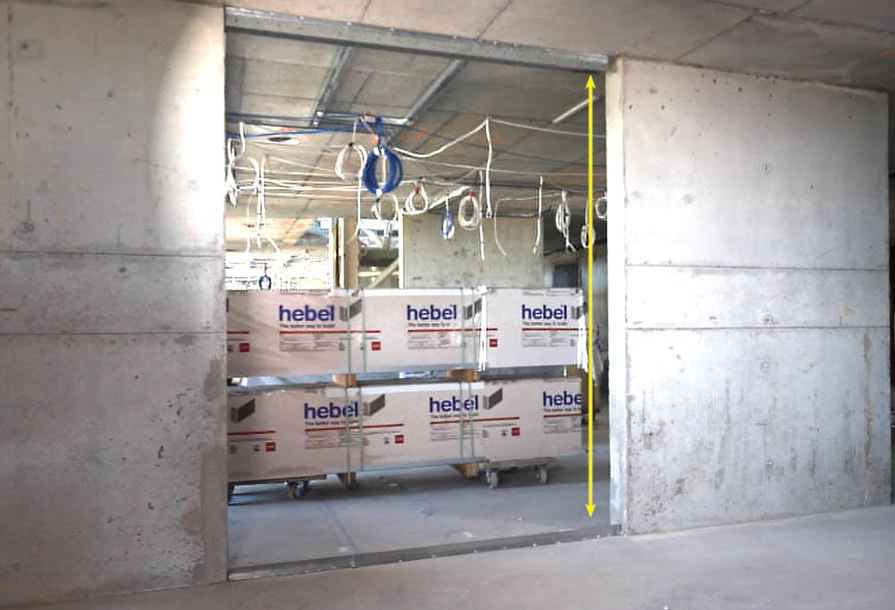 Check the distance between the slab and soffit against the Hebel PowerPanel length, allowing for a minimum 15mm gap between the top of the panel and the head angle. In most cases if you’ve ordered made-to-length panels they’ll go straight in as is. However, if the concrete pour is out you may need to either cut the panels or pack the panels at the base.
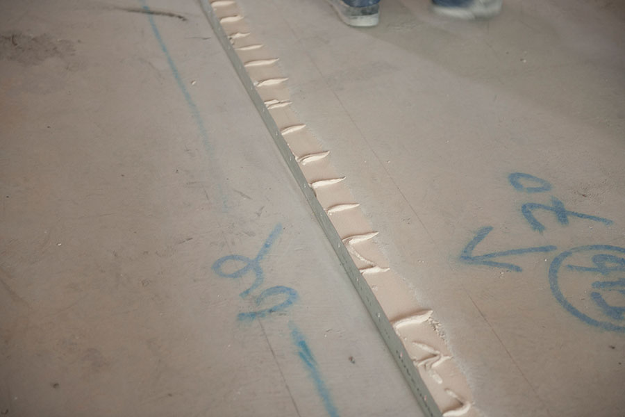
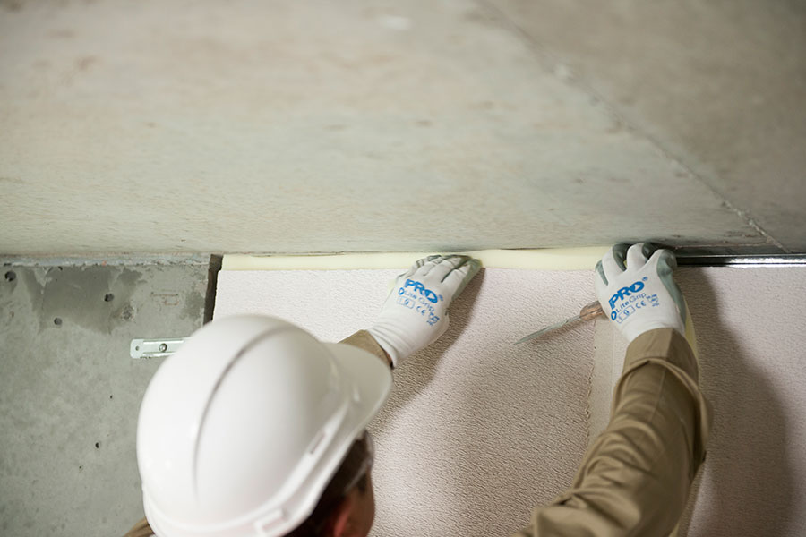
STEP 3 Mix and apply Hebel Adhesive (or Hebel Mortar) at base
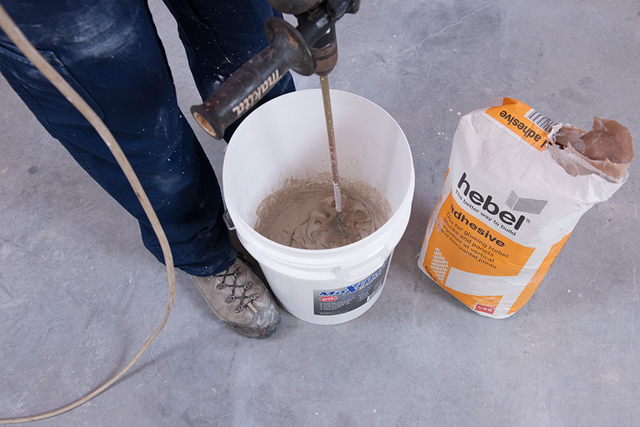 When mixing Hebel Adhesive or Hebel Mortar refer to the instructions on the packaging.
 The purpose of both Hebel Adhesive and Hebel Mortar is to act as a leveller and provide fire and acoustic protection.
If the gap at the base is 3mm or less use Hebel Adhesive and apply it with a trowel.
If the gap is more than 3mm, pack it up using Hebel Mortar and also apply with a trowel. Use packers if necessary. When you use Hebel Mortar to fill gaps over 3mm, it’s important to make sure the mortar is no more than 15mm thick.
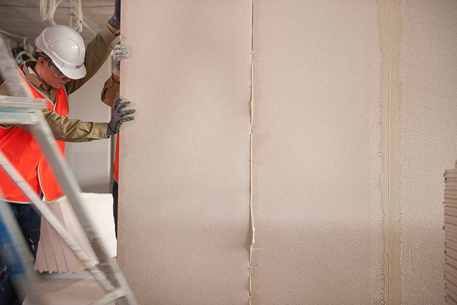
STEP 4 Install Hebel PowerPanel wall leaf
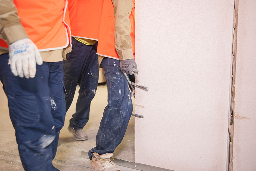
With the Hebel Adhesive (or Hebel Mortar) already applied at the base, place a Hebel PowerPanel between the base and head angle using the Hebel panel trolley. For its final positioning use either an e-lifter or a pinch bar.
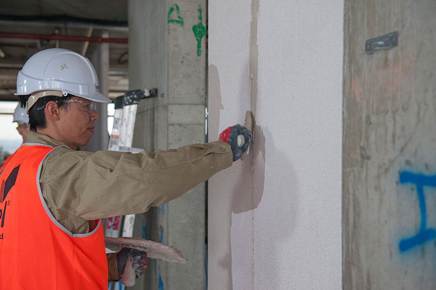
STEP 5 Apply Hebel Adhesive at joints
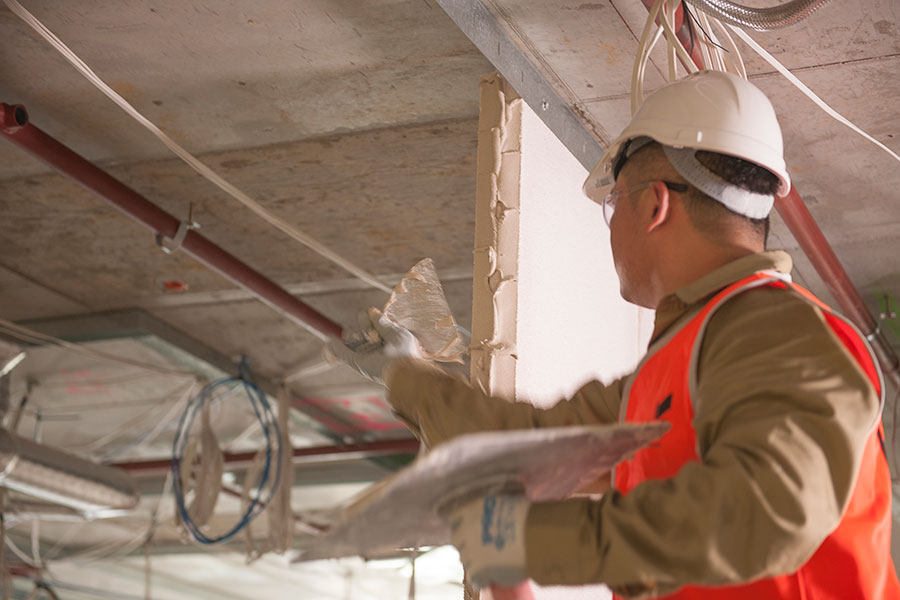
 For the panel joints it’s important to apply adhesive correctly because it forms part of the fire and acoustic protection for the wall. Use enough Hebel Adhesive to form a joint that’s 2 to 3mm thick when the panels are pushed together. Make sure there’s adhesive right across the panel depth.
Make sure you use sufficient Hebel Adhesive and pressure so the panel is fully bedded against the other panel throughout the joint.

Next fix the panel to the slotted head and base angles. Use a minimum of two screws per panel and no less than 50mm from the end of each panel.
Check that you’re using the correct screws and spacing for the particular application. See the Design and Installation Guide for further details.
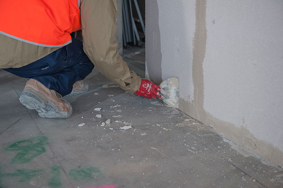
Once the panel is fixed in, scrape off any excess adhesive or mortar at the base or protruding from joints.
If there are any visible gaps fill them with Hebel Adhesive.
Simply repeat this step for each PowerPanel until the wall section is completed.
STEP 6 Apply Hebel Patch on the Hebel PowerPanel if required
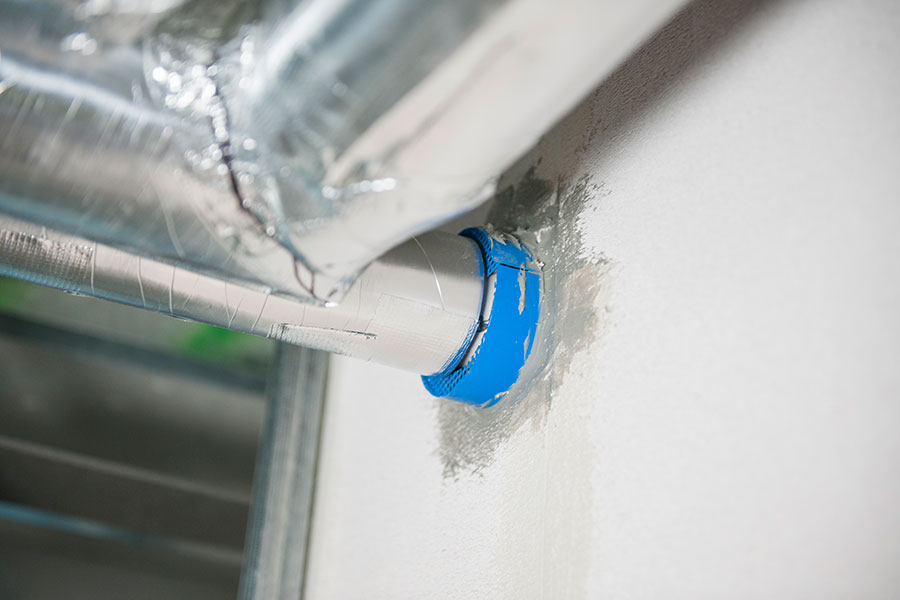
STEP 7 Install backing rod and apply CSR FireSeal sealant at angle as required
 Firstly, install the backing rod to the manufacturer’s specifications. The placement of the backing rod is important and should be placed at a minimum of 10mm from face of panel. The backing rod is installed to control the depth of the sealant.
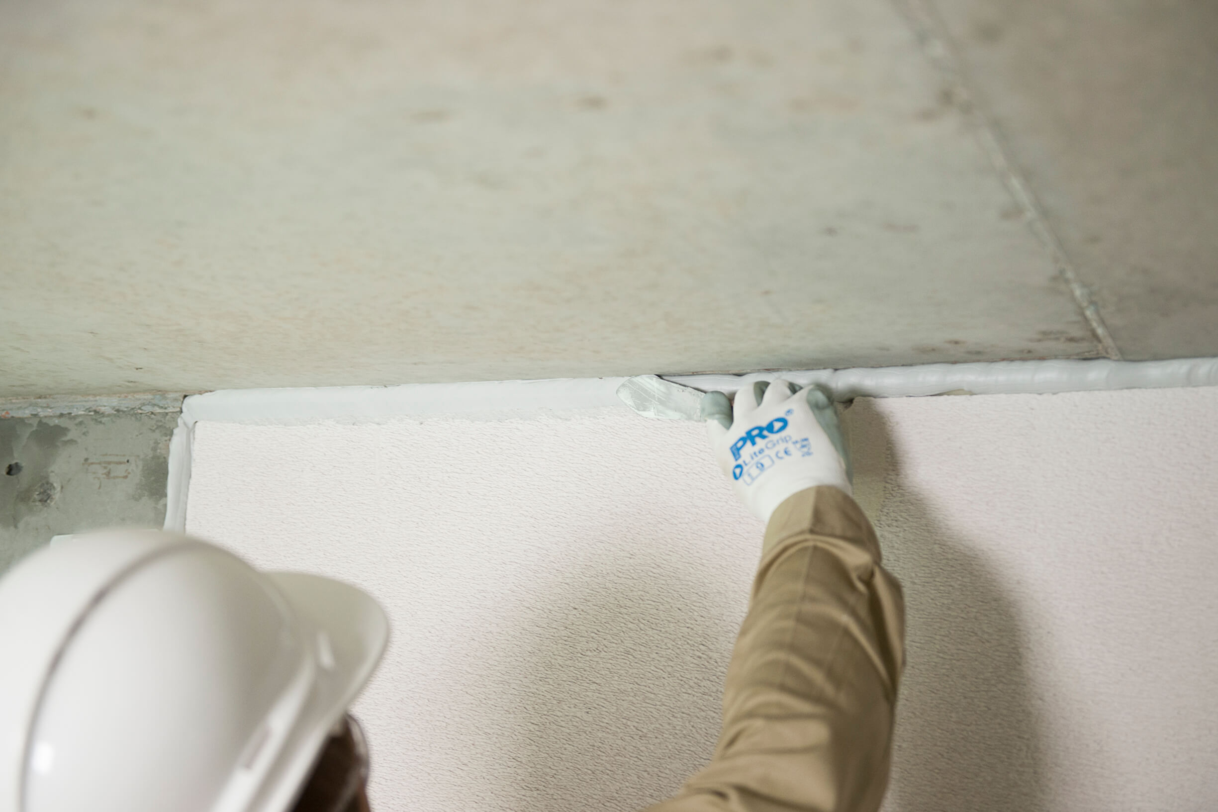 Once the backing rod is in place, apply CSR FireSeal to a minimum depth of 10mm. As with the backing rod, care should be taken applying sufficient CSR FireSeal correctly as it’s also an essential part of fire and acoustic protection. The minimum depth of 10mm is required in all applications.
There are variations in the maximum depths needed. This information is provided in the Design and Installation Guide. Also note that in some instances, such as a panel to column junction, fire-sealing needs to be done in more than one position. Again this information is in the Design and Installation Guide.
WALL FRAMES (one or two sides)
STEP 1 Install steel stud framing
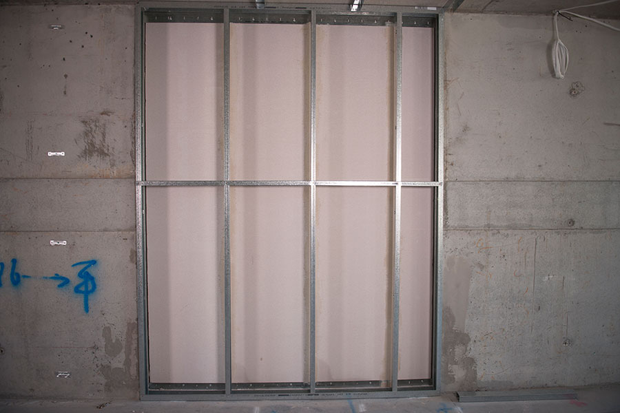 The steel stud framework needs to be installed to the manufacturer’s specifications. The zinc coated steel framing is made up of steel studs, noggings and head and base tracks which create a separate stud framework, which in conjunction with the Hebel PowerPanel, provides an asymmetric cavity wall assembly. Please ensure that the cavity spacing is at least the same or larger than the design.
STEP 1 Install furring channels – one side only
- Furring channel mounting clip installation
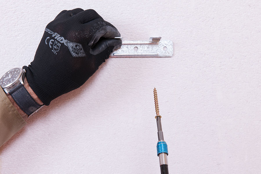 Furring channel mounting clips are proprietary components enabling the mounting of furring channels and plasterboard onto Hebel PowerPanel. This provides a cavity space which can change the acoustic insulation performance of the wall system. Please ensure that the cavity spacing is at least the same or larger than the design.
In a typical application furring channel clips are installed at maximum 600mm horizontal spacings and 1200mm vertical spacings. BetaGrip1 (BG01) clips are used on Hebel Intertenancy and Corridor walls systems.
- Installing furring channels
Mount the Rondo galvanised steel furring channels (Nº129, 28 x 38 x 0.50mm BMT) onto BetaGrip clips and fit into soffit and floor tracks, making sure they extend all the way to the floor. For further information refer to manufacturer’s literature.
LININGS
STEP 1 Install services as required
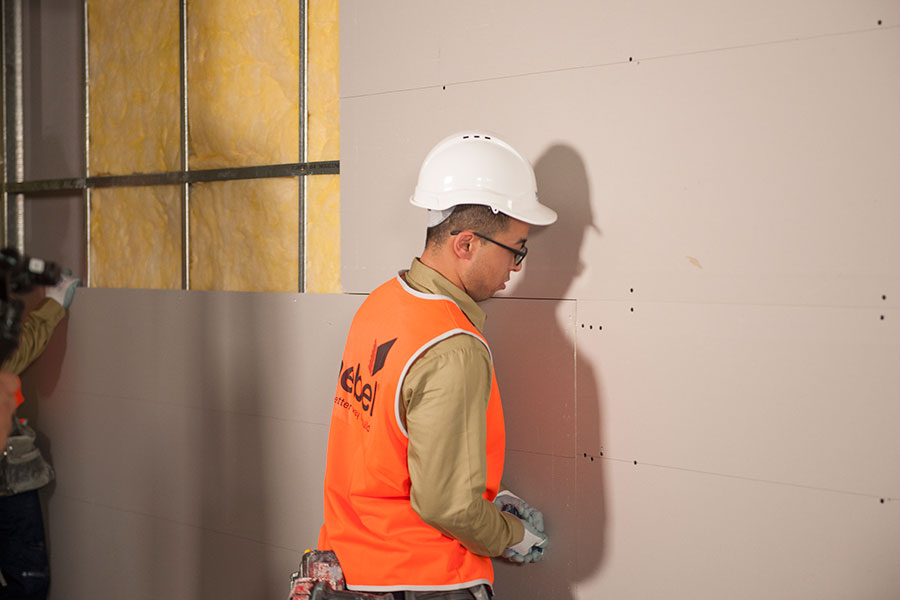
STEP 2 Install Bradford or Martini insulation
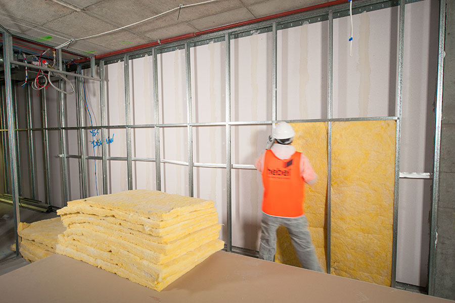 Install the insulation according to the system specification and follow the installation guidelines available from CSR Bradford and CSR Martini. Importantly, the thickness of insulation should fully fill the cavity between steel stud framework or furring channels and should reach from concrete slab to concrete soffit. If there is any gap in the insulation the acoustic performance of the system may be adversely affected.
Note: Bradford Fireseal insulation is typically used in junctions of intertenancy and external brick walls.
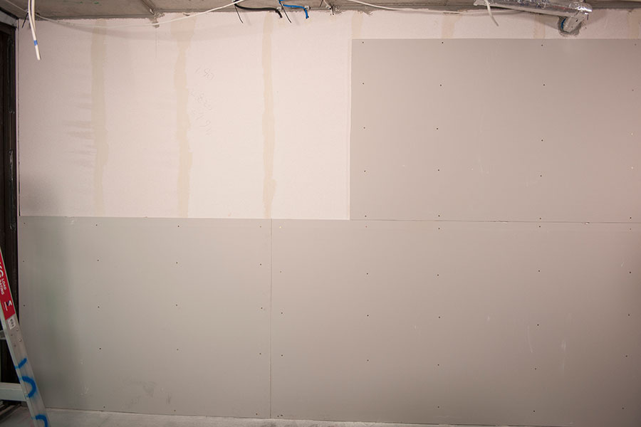
STEP 3 Install Gyprock® plasterboard wall lining
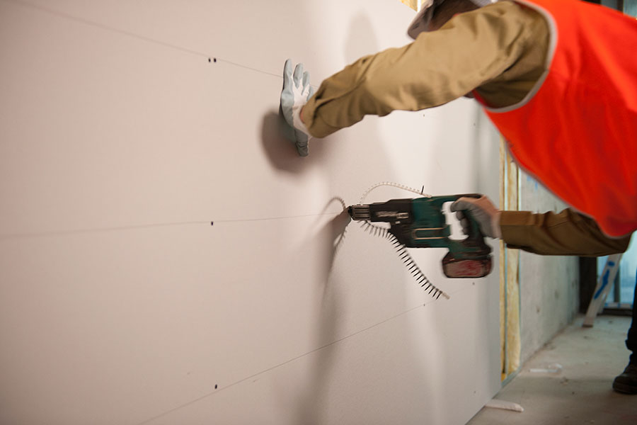 The plasterboard sheets must be cut to fit neatly and should not be forced into position. The plasterboard needs to extend to at least the ceiling level. It’s important to screw-fix only because gluing sheets can adversely affect acoustic rating of system.
In Hebel Intertenancy and Corridor walls systems plasterboard can be fixed directly to Hebel PowerPanels, the furring channel and the steel stud framework:
- Direct fix to Hebel: the plasterboard needs to be installed in accordance with the Gyprock® plasterboard installation guidelines. Appropriate screws must be used to secure in position (see Hebel Design and Installation Guide).
- Fit to furring channel or stud frame: the plasterboard needs to be installed in accordance with the Gyprock® Steel Frame Wall Systems Installation Guide, NºGYP544.
The minimum mass of plasterboard must be 8.5kg/m2.
Gyprock plasterboard handling and installation guidelines are available through CSR Gyprock.
STEP 4 Install control joint backing rod and sealants
 Control joints need to be provided at maximum 6 metre spacings with a 10mm minimum between the Hebel PowerPanel and the other building component. Control joints also need to be provided to coincide with any control joint in the main structure. The slotted head angle and base angle must be discontinuous at a structural control joint. Please refer to the Design and Installation Guide for control joint construction details.